 Contributed by Ian Hamilton, Geologist, PPM Consultants
Locating objects like water pipes or electrical conduits is an important first step before drilling. Leaking Underground Storage Tank (LUST) project managers commonly use Ground Penetrating Radar (GPR) as a method for mapping these underground features. GPR has other capabilities, however, and utilizing them may increase efficiency in remediation by enhancing the subsurface model.
PPM Project Managers Connor McCluer and Jacob Pongetti have both written blog articles on the benefits of using High Resolution Site Characterization (HRSC) to create a 3-D conceptual model of the subsurface. HRSC requires a direct push rig and trailer, so, in most cases, an 811 call and a GPR survey are required before mobilization. If a GPR unit is on site already, what other data can it provide?
As opposed to borehole geophysics, GPR is a cheap, non-intrusive, surface geophysical method of characterizing subsurface properties. Other important surface methods include Electrical Resistivity Imaging (ERI), seismic refraction, self-potential, and gravity analysis. For civil engineering and construction purposes, GPR is the most commonly used surface geophysics method. The units are small, easy to transport carts that are rolled along by a technician walking behind it. No probes or borings are required to run the test, and most are outfitted with a GPS unit to record exact location along the path.
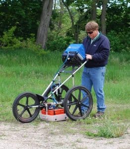
Source: Get the Basics on Ground Penetrating Radar (goslingczubak.com)
A GPR unit transmits radio wave pulses at select frequencies into the ground and receives the energy reflected back by the interface with different materials (specifically those with differing dielectric permittivity). That is, the unit reads when something is different in the subsurface. In the example below, the radio waves are being reflected by the pipe, by the water table and by the soil to bedrock interface.
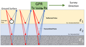
Source: Ground Penetrating Radar (GPR) | US EPA
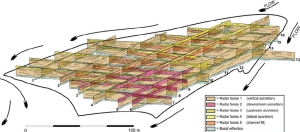
GPR, then, can detect underground infrastructure, map soil depth, and detect the groundwater surface. It is also used to identify karst features, tunnels, burrows, voids, fractures, soil gas/moisture, roots, soil horizons, rock fabric, compaction and even groundwater contamination. More than just point data, these sensed objects and interfaces can be applied as far as the survey was long. Moreover, adding transecting GPR lines creates 3-D visualization of features in the form of a fence diagram.
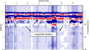
Conceptualizing the site in 3-D allows for more informed hypotheses about drilling placement, local groundwater flow paths and subsequent plume migration. In select cases, GPR may even be useful for delineating the areal extent of a contaminant plume. Common non-aqueous phase liquid (NAPL) contaminants have been shown to have low dielectric permittivity compared to water, allowing differentiation of the plume from the non-contaminated groundwater. The GPR can read this permittivity change as an increase in electromagnetic wave propagation velocity, a change in reflectivity and/or a change in electric conductivity. The changes are seen as shadows or halos in the reflection image or as a drop in the location of groundwater reflection. In the example below, the areas of shadow in the image resolution are petroleum contamination.
GPR providers will generally pinpoint features on their scan that pertain to stated goals. So, if they know the main purpose of the scan is to identify USTs or buried lines, the provider report will focus on those features. Experienced GPR project managers, however, will also notice additional patterns, shadows and anomalies. Ask your GPR contractor to discuss these with you and how they might affect drill placement. For example, if a GPR profile pattern appears to be the soil-bed rock interface and a wide anomaly exists above it, it may be an indication of a boulder to be avoided by a direct push or rotary rig. Or, if a GPR profile pattern appears to be the water table contact and a wide shadow exists within it, it may be an indication of a NAPL plume that should be targeted for a sampling well. If the plume is verified, using GPR to outline the plume would be a best practice.
Detection of USTs and transmission lines is our most common use of GPR, but it has proven itself as a solid method of retrieving geophysical data in many environments. GPR has some limitations, however, in that wave resolution and penetration can be affected by subsurface interferences like densely packed rebar, clay layers, wire mesh or other conditions. While methods exist to better resolution in suboptimal situations, its use for detailed geophysical analysis is highly dependent on the situation in the subsurface. This is one reason why methods like ERI and HRSC are the preferred geophysical data gathering methods for delineating residual and floating product plumes. However, as GPR is on site already as a common step for many projects, it makes sense to try and obtain as much useful data as possible from its scans.
References:
Bradford, J. and Babcock, E. “The Need to Adapt the Exploration Model from the Oil Patch to Contaminated-Site Characterization: A Case from Hill AFB, Utah, USA.” Center for Geophysical Investigation of the Shallow Subsurface Publications and Presentations. July 2013.
Bradford, J. and Deeds, J. “Characterization of an Aquitard and Direct Detection of LNAPL at Hill AFB Using GPR AVO and Migration Velocity Analyses.” United States: N. p., 2002. Web. doi:10.2172/833500.
Ch, S.R., & Chandrashekhar (2014). Detecting oil contamination by Ground Penetrating Radar around an oil storage facility in Dhanbad, Jharkhand, India.
Environmental Geophysics. “Ground Penetrating Radar (GPR).” EPA.gov. Ground Penetrating Radar (GPR) | US EPA
Ferry, et. al. “Ground Penetrating Radar Investigations along the North Anatolian Fault near Izmit, Turkey: Constraints on the Right-Lateral Movement and Slip History.” Geology. Jan. 2004. pp. 85-88.
Johnson, D. “Use of Ground Penetrating Radar for Water Table Mapping, Brewster and Harwich, Massachusetts.” USGS Water Investigations Report 90-4086. 1992.
Mansi, A.H, Castillo, M.P, and Bernasconi, G. “Controlled Laboratory Test for the Investigation of LNAPL Contamination Using a 2.0 GHz Ground Penetrating Radar.” Bulletin of Applied and Theoretical Geophysics. Vol. 58, no. 3, pp. 169-180. Sep. 2017.
McNaughton, CH. 2011. Monitoring a Shallow Gasoline Release Using GPR at CFB Borden.
Master’s Thesis, University of Waterloo.